A thermal bridge is a place where heat crosses the envelope faster than through the surrounding construction: a balcony slab, a window reveal, a wall meeting a floor. The psi-value puts a number on that extra loss per metre of junction, calculated to BS EN ISO 10211, and PHPP sums every metre of every one.
What counts as a thermal bridge?
Three distinct things get called thermal bridges, and they are handled differently in the calculations.
Geometric bridges happen wherever the envelope changes direction. An external corner has more outside surface than inside surface, so the geometry alone concentrates heat flow, even with perfect insulation throughout.
Repeating bridges are regular interruptions within an element: timber studs through insulation, mortar joints, wall ties. These do not get psi-values. They belong inside the element’s U-value, as the Passive House Institute’s guidance on thermal bridge free design makes explicit, so a timber-frame wall U-value that ignores its studs is simply wrong before any junction is considered.
Linear bridges are the junctions: floor to wall, wall to roof, window to wall, anywhere two elements meet and the insulation line is interrupted or pinched. These are the ones that carry psi-values, denoted Ψ and expressed in W/mK, heat loss per metre of junction length per degree of temperature difference.
What exactly is a psi-value?
A psi-value is a correction. You model the real junction in two-dimensional finite element software to BS EN ISO 10211, calculate the total heat flow through it, then subtract the heat flow the plain elements would account for on their own. Whatever is left over, positive or negative, is the psi-value. The Passive House Institute sets out the method in its basic principle for calculating thermal bridges, and the dimensional convention matters: PHPP measures the building by its external dimensions, so psi-values must use the same reference.
That convention produces a result that surprises people: negative psi-values. An external corner measured externally counts some heat loss area twice, so a well-insulated corner junction can come out below zero. A whole envelope where the psi contributions sum to zero or less is formally “thermal bridge free”, and the practical screening threshold is Ψ ≤ 0.01 W/mK per junction.
In practice we run these calculations daily. A typical 2D detail takes a few hours to model and verify, which is why our published rate for a 2D thermal bridge calculation is €500 per detail, and €1,500 for a 3D one.
Why do default psi assumptions wreck PHPP results?
Because the defaults are guesses, and the junctions are long. A standard semi-detached house has well over 100 metres of floor-to-wall, eaves, verge, party wall and window junctions. Pick a blanket allowance instead of calculated values and you can be out by a large slice of the heating demand in either direction. The PHI reports built examples where unresolved thermal bridges added up to 14 kWh/m²a of heating demand, against a Passivhaus budget of 15. The junctions alone can spend the entire budget.
The error cuts both ways, and the optimistic direction is worse. In the PHPP files we review for certification, a recurring pattern is a model that sails through at design stage on assumed psi-values, then fails when the real details are calculated. By that point the slab is poured and the cheap fixes are gone. The pessimistic direction wastes money differently: clients upgrade glazing or add insulation to offset junction losses that a calculation would have shown were never there.
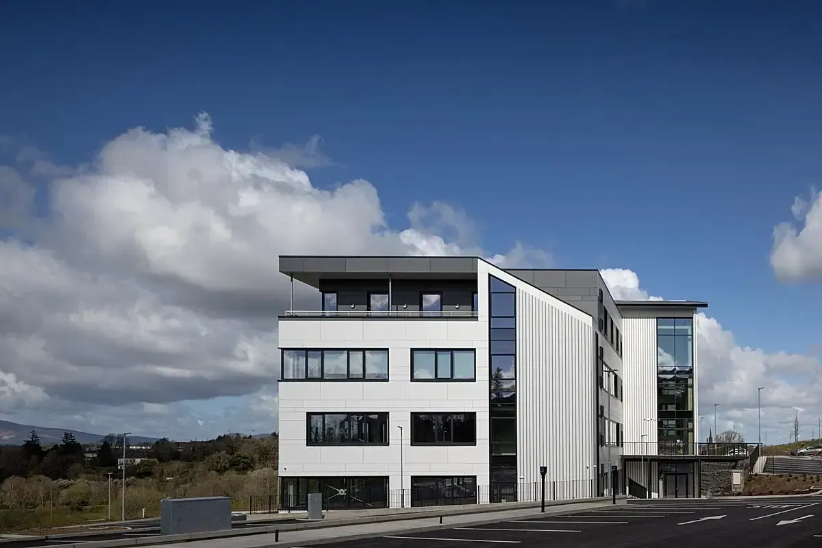
At Senan House in Enniscorthy, Ireland’s first certified Passivhaus office, the junctions were calculated rather than assumed from the outset, which is what let a steel-framed commercial building meet the standard without padding the specification as contingency.
What drives the psi-value at each junction?
| Junction type | What drives its psi-value |
|---|---|
| Ground floor to wall | Thermal conductivity of the first blockwork course; whether floor and wall insulation connect |
| Window to wall | Position of the frame relative to the insulation layer; reveal, sill and head overlap |
| Eaves and verge | Continuity between wall and roof insulation; timber content at the wall plate |
| Balcony and canopy | Whether the slab penetrates the insulation; structural thermal break or bare concrete |
| Party wall to external wall | Cavity closure detail; whether the party wall bypasses the insulation line |
| External corner | Mostly geometry; usually small or negative when insulation is continuous |
The base-of-wall junction deserves its own sentence. The PHI’s worked examples show that swapping the bottom course of blockwork for a low-conductivity block, with λ below about 0.25 W/mK, takes the detail to thermal bridge free, while standard dense blocks at λ above 0.8 W/mK leak substantially. One course of different blocks, ordered before the brickie arrives, is the difference.
When does a junction become a mould risk?
Heat loss is only half the problem. A junction that leaks heat has a cold internal surface, and a cold surface in a humid room grows mould. The check is the temperature factor f_Rsi, a dimensionless number between 0 and 1 describing how close the internal surface temperature stays to room temperature. The threshold to design to is f_Rsi ≥ 0.75 under EN ISO 13788, and the calculation comes out of the same ISO 10211 model as the psi-value, run with an increased internal surface resistance of 0.25 m²K/W to represent furniture, curtains and still corners.
On site this shows up exactly where the numbers predict: behind wardrobes against external walls, in the corner above a window head, along the skirting at a slab edge. If a junction calculation returns f_Rsi below 0.75, the detail gets redesigned, not explained away. Our condensation and dew point tool covers the related surface and interstitial checks for plain elements.
When do you need 3D instead of 2D?
Most junctions are genuinely two-dimensional: a long, uniform cross-section, like an eaves running the length of a roof. A 2D model to ISO 10211 is the right tool and the affordable one. Three-dimensional modelling is needed when heat flows in all three directions at once.
- Point penetrations. Steel beams, columns or brackets passing through the insulation produce point losses (chi-values, in W/K) that no 2D section can capture.
- Three-plane corners. Where two walls meet a floor or roof, the coldest point sits in the corner itself, and only a 3D model finds the true f_Rsi.
- Intersecting junctions. A balcony door threshold meeting a slab edge and a party wall is one detail, not three, and modelling it as three 2D sections misses the interaction.
- Certification disputes. When a marginal building needs every junction sharpened, 3D results replace conservative 2D approximations.
The cost difference is real, roughly threefold per detail, which is why a competent consultant runs 2D wherever the geometry allows and reserves 3D for the details that need it.
Where Mosart fits
Junction calculation is a standalone service at Mosart: 2D and 3D models to BS EN ISO 10211, at the rates published above, with the verified psi-values and f_Rsi results feeding straight into PHPP. For a first estimate of what a junction is costing you, start with our free thermal bridge tool.